Making your first combat robot
Making your first combat robot
Our internal competition is for antweight robots, meaning a weight limit of 1 lb (454 g). We follow the SPARC rules, which you should read (they're not long).
This tutorial assumes you're making the most common type of antweight design: two drive wheels and one weapon motor with a spinning kinetic weapon. You don't have to make a bot like that, but it's a good place to start.
Components and general layout
The basic combat robot doesn't have any code or autonomy -- it's plain remote control, like an RC car. We use the following components:
- Lithium Polymer (LiPo) batteries, typically of the "2S" (7.4V) variety. These connect with a yellow XT30 plug, but also have a white connector used only for charging. Example.
- NOTE: LiPo batteries can be dangerous! Don't over-drain them, puncture them, or short them out. If you do, they may swell, become hot, and even shoot fire. Dangerous-looking batteries go in the "oh crap" metal box in the Foundry, or in the team's sand bag.
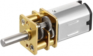
- Brushed DC motors. Used to drive the wheels. We typically use "N20" model motors, which have a little integrated gearbox. Example.
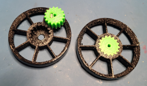
- Wheels. We mostly use "Tyler wheels", a two-part 3D printed design that Tyler Bletsch came up with. Some groups order commercial wheels or do something else instead. If you give a desired diameter in #3d-printing on Discord, Tyler will print some for you. CAD.
- Brushed Electronic Speed Controller (ESC). An electronic component that listens to the radio receiver and governs brushed DC motor speed and direction accordingly. We use a model that controls two motors from one unit: example.
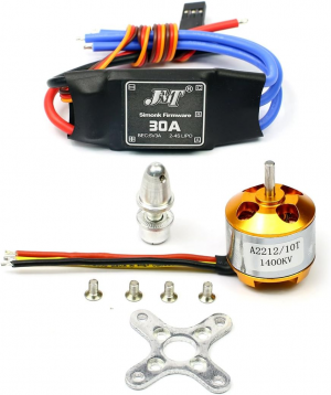
- Brushless DC (BLDC) motors. Used for spinning kinetic weapons. These have 3 wires instead of 2, and need a different kind of controller. They get to crazy fast speeds. We most commonly use A2212, but some groups use RS2205, which is more fragile but has an easy to use screw shaft.
- Brushless Electronic Speed Controllers (ESC). Listens to the radio receiver and governs the brushless DC motor speed. Example.
- Electrical connectors. We use various wire and electrical connectors, including:
- XT30: Yellow, two conductor, can only be plugged one way. We use these for all high power connections (battery, brushless ESC)
- JST: Red, two conductor, can only be plugged one way. Lower current than XT30, these are what come on the brushed ESCs, and what we solder onto the brushed motors.
- Switch and LED. You gotta have a power switch that is externally accessible. The cheap and easy option are automotive rocker switches (example), but more ambitious groups can use screw switches to prevent accidental deactivation of your robot.
- Radio transmitter/receiver. We use standard RC transmitters and receivers. Example.
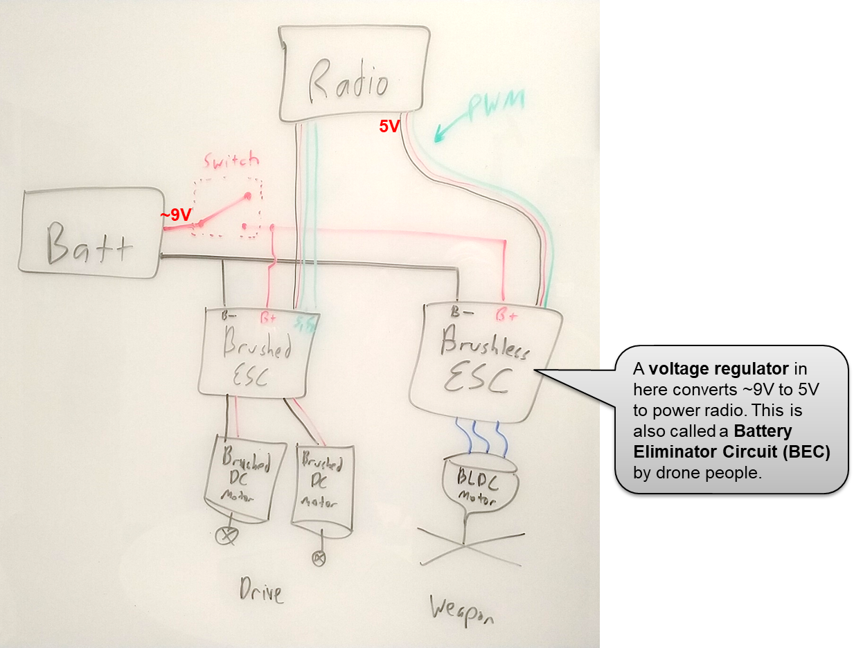
The electrical layout of the above typically looks like this:
We'll cover how you achieve this below.
Wiring harness
Your first task will be to solder a bunch of wires together to run power to everywhere you need it; this is called a wiring harness. Here's the schematic:
Use the 18AWG red and black wire we have. To solder XT30s, you can follow this video. I recommend these steps:
- Gender: Determine which XT30 gender you need. Note: connector genders are based on the shape of the METAL, not the plastic -- the XT30 male is the two protruding prongs inside the recessed plastic housing.
- Polarity: Look at the embossed + and - on the connector. I recommend marking - with a black sharpie (or + with red) on the connector you intend to use
- Plug a spare of the opposite gender into the one you intend to solder. This will prevent warping during soldering.
- Cut/strip wire so only about 4mm is exposed (see video)
- Remember heatshrink tube! Put about 1cm of tube loosely on each wire.
- Don't forget the heatshrink tube! Once you solder, you can't put the tube on, and you'll have to desolder.
- Actually don't forget the heatshrink tube! It's easy to forget, so I put it three times here.
- Tin the back of the XT30 with generous solder on both + and -. Also tin the exposed wire. ("Tin" just means to melt solder into it)
- Melt each wire into the solder on the connector
- Shrink the heatshrink tube with a heat gun. You did remember heatshrink tube, right? By the way, don't use the soldering iron to shrink it, use an actual heat gun.
Soldering to the switch is quite similar. Again, don't forget heatshrink tube!
Scrap bot
With that done, you can slap all the components together onto a piece of scrap garbage and drive it around! Just plug stuff up as shown in this diagram:
Notes:
- The channel numbers on the receiver correspond to axes on the transmitter. Channel 1-4 are the left/right X/Y axes, but it's basically random which is which. Channel 5+ are the knobs/switches at the top of your transmitter. Use trial and error to see what's what, and I recommend labeling your transmitter's axes with gaffer tape once you figure it out.
- The three-conductor wires are either black/red/white or brown/red/yellow. Either way, this corresponds to ground/power/signal. Signal (white/yellow) goes toward the numbers on the receiver!
- The vertical axes of the radio that has no spring to it ("throttle") is a good candidate for your brushless motor weapon.
- The dual brushed ESC has two inputs: black/red/white and a single yellow. These two signals, by default, do "differential" drive, meaning that one signal wire is "forward/backward" and the other is "steering". Which one is which is arbitrary based on how you built things. You can force it to be "axis1 = motor1, axis2 = motor2" by flipping the little switch on the brushed ESC.
- The two axes on the other stick are good candidates for "forward/back" (Y) and "steer" (X) for the dual brushed ESC.
- This is all trial and error, so hook it all up, and see what controls what.
- If everything is basically right except for an axis being inverted, enable the reverse setting for that axis. Most of our transmitters have a simple toggle switch for this.
- The brushless ESC came from flying drones, so it has a safety mechanism to it. The throttle for the brushless must be set to zero for a few seconds before it will enable. When disabled, the motor will make a periodic regular beep. When enabling, the motor will play a little affirmative bip-bip-bip-beeeep tone, then you're clear to throttle up. Sometimes you need to "calibrate" the ESC by sweeping throttle all the way up and down its movement, then leaving it to zero for few seconds to enable.
Using the above tips and some trial and error, get your transmitter doing what you want to the motors, stick everything onto some junk and drive your junk bot! Once you're driving a junk bot, you're ready to design your real robot.
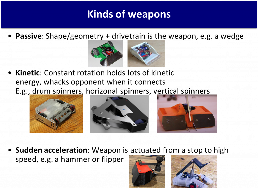
Common robot designs
I need to add more content here, but here's a placeholder to get started. Research these categories and figure out what you wanna do. For your first robot, kinetic weapons are strongly recommended.
Fabrication tips
CAD Modeling
To design your robot, you will need to use a CAD software to build the model for prototyping, printing, and fabrication. Solidworks, Onshape, and Fusion360 are all options that can be used. Onshape works like google docs for CAD, letting different users easily edit the same model in the cloud, Solidworks is the most widely used and known, and Fusion360 works on MacBooks (Solidworks doesn't). When building your model, it's a good idea to keep in mind the size of your electronics, as they need to all fit inside the chassis of your robot. To make things easier, this google folder contains step files with models of all of the main electronic components you will have in your robot.
Weapon hubs
(I need to expand on this) A hub affixed to the BLDC motor is the most common way of coupling a weapon to it. The common cheap and reliable solution is an A2212 motor with a TPU hub that hugs the entire body of it retained by a 1/8" shaft collor on the output shaft. The weapon is then mated to this hub via friction or fasteners.
Tip: if your weapon can slip with respect to the motor, that will help to protect the motor from shock loads during hits.

